
ESE101: Finally an MSP430 Timer Example!
Last time, I went through the MS430 User’s Guide's timer diagrams to explain how MSP430 timers are configured. This time I’ll (finally!) show you code to configure a timer and blink a light.
Reminder from last time:
- Our timer/blinking light example is going to use the MSP430’s Timer A0 (TA0) with the ACLK as its input clock.
- ACLK runs at 32768 Hz.
- We’ll configure both input dividers into TA0 as divide-by-1, so TA0 will run at the same frequency as ACLK, which is 32768 Hz.
- We’ll configure TA0 in continuous mode, which means it will repeatedly count from 0x0000 to 0xFFFF.
- We’ll configure TA0 to give an interrupt every time the timer overflows from 0xFFFF to 0x0000.
- Each time the TA0 interrupt fires we’ll toggle an LED.
- We expect TA0 to overflow every 2 seconds.
Here’s the picture that shows how we’ll configure our timer:

I’ve written the code for our Assembly Language Playground. I’ll introduce each part of the code in turn; please see the very end of this post for all the code in one copy-and-paste-friendly block.
We start by setting GPIO P1.0 as an output. That’s the pin connected to the LED we’ve been using for most of our examples. Then we enable interrupts since we’ll be using TA0’s interrupt later. This code is the same as in our previous interrupt example:
           ; Set GPIO P1.0 to be an output
           BIS.B      #1, &PADIR_L

           ; Enable interrupts
           NOP
           BIS #GIE, SR
           NOP
Next we’ll start the new stuff: configuring the timer.
First we’ll configure the input clock and dividers with the TASSEL, ID, and IDEX configuration bits in the TA0CTL and TA0EX0 registers. Here are the relevant sections from the MSP430 User’s Guide:
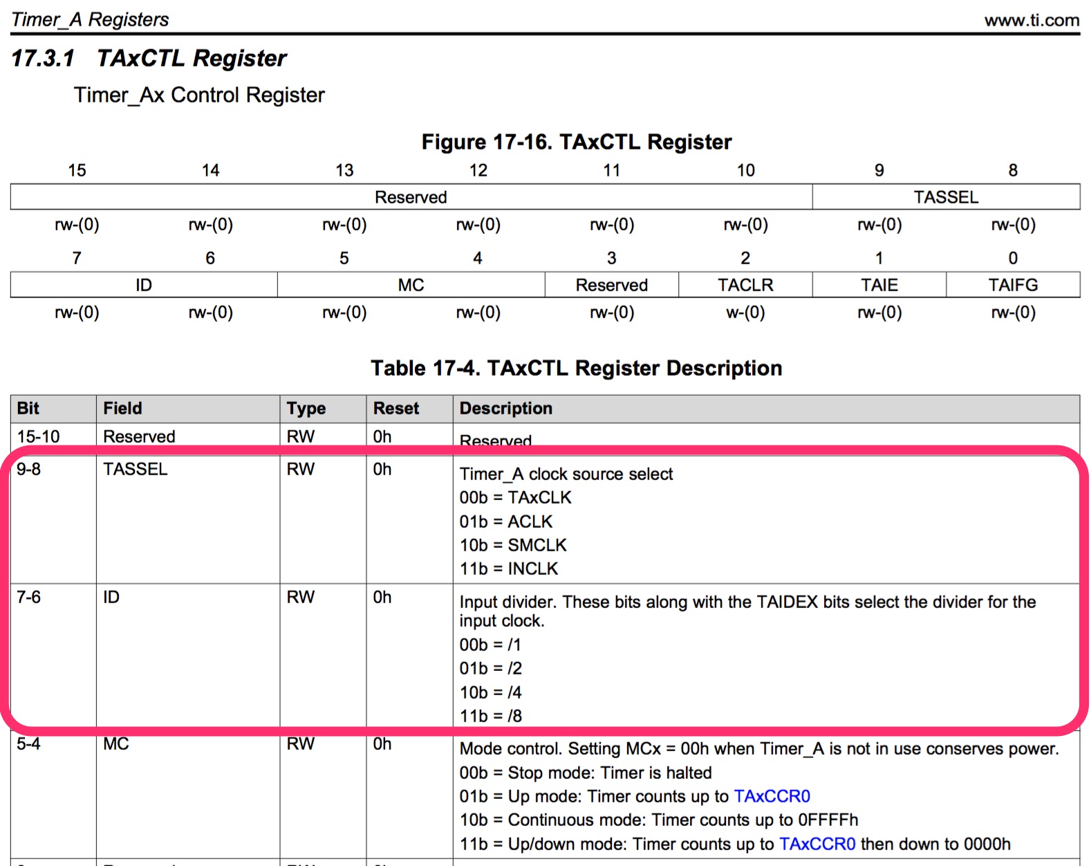

We set TASSEL equal to 1 to select ACLK, and then set both ID and IDEX to 0 to select /1. We could use the numbers “1” and “0” for the register values in the assembly code, but TI has header files with handy configuration register definitions, and so:
- We’ll use #TASSEL_1 to set the TASSEL bits to 1 like this:
BIS #TASSEL_1, &TA0CTL ; TASSEL == 1 selects ACLK
We’ll use #ID_0 to set the ID bits to 0 like this:
BIS #ID_0, &TA0CTL ; ID == 0 selects /1
We’ll use #TAIDEX_0 to set the IDEX bits to 0 like this:
BIS #TAIDEX_0, &TA0EX0 ; IDEX == 0 selects /1
The header file is called msp430f5529.h, and it lives in /Applications/ti/ccsv6/ccs_base/msp430/include/msp430f5529.h on my Mac installation of Code Composer Studio. Check it out to see all the definitions that TI gives you. Here’s the parts of that header file that we’ll be using:
#define TASSEL_1 (1*0x100u)  /* Timer A clock source select: 1 - ACLK  */
#define ID_0     (0*0x40u)   /* Timer A input divider: 0 - /1 */
#define TAIDEX_0 (0*0x0001u) /* Timer A Input divider expansion : /1 */
And here’s our code code that uses them:
           ; Configure ACLK as the timer clock source, with both the
           ; ID and IDEX dividers set to /1.
           ; ACLK runs at 32768 Hz, and so will the timer.
           BIS #TASSEL_1, &TA0CTL   ; TASSEL == 1 selects ACLK
           BIS #ID_0, &TA0CTL       ; ID == 0 selects /1
           BIS #TAIDEX_0, &TA0EX0   ; IDEX == 0 selects /1
We’ve configured the timer’s clock source. Next we’ll configure TA0 to generate an interrupt each time it overflows as it increments from 0xFFFF to 0x0000. The TAIE bit controls the interrupt enable, in the TA0CTL register:
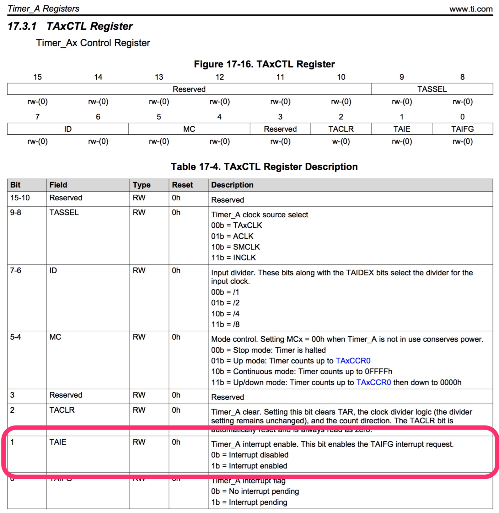
TI gives us the helpful #TAIE value to set that bit to 1:
           ; Configure timer to interrupt on overflow.
           BIS #TAIE, &TA0CTL
And finally we’ll finish configuring the timer mode by setting the MC bits in TA0CTL:

We’ll use TI’s #MC_2 definition to set the MC bits to 2 (which is ‘10’ in binary):
           ; Configure timer in continuous mode.
           ; Setting MC to anything other than 0 also starts the timer, so we
           ; want to do this as the last timer configuration step.
           BIS #MC_2, &TA0CTL       ; MC == 2 selects continuous mode
We’ve completed configuring the MSP430 timer - great! However, we aren’t done yet. We still need to write the interrupt handler and make sure the processor knows to call the handler when the timer interrupt happens.
We’ll use a simple main loop that does nothing forever:
MainLoop:  ; Do nothing, all action is in the interrupt
           JMP MainLoop
Now we need to write the TA0 interrupt service routine (ISR) that gets called each time the TA0 overflow interrupt happens:
TA0_ISR:
           ; Clear the interrupt flag.
           BIC #TAIFG, &TA0CTL

           ; Toggle GPIO P1.0
           XOR.B      #1, &PAOUT_L

           RETI
Each time the interrupt fires we:
- Clear the TAIFG interrupt flag bit to acknowledge that we handled the interrupt.
- Toggle the GPIO connected to the LED to turn it on/off.
- Return from the ISR with the RETI instruction.
Now that we’ve written our ISR, we have to tell Code Composer Studio that we’ll be using that ISR for the TA0 overflow interrupt, and for that we’ll have to find that interrupt’s vector address.
You can usually find a list of interrupts and the interrupt vector addresses in a microcontroller’s programming reference or the datasheet. TI puts it in their datasheet section under “Interrupt Vector Addresses” for the MSP430F5529: here’s an online version, and here’s a pdf.
Here’s the list of the MSP430F5529 interrupts with TA0’s circled:
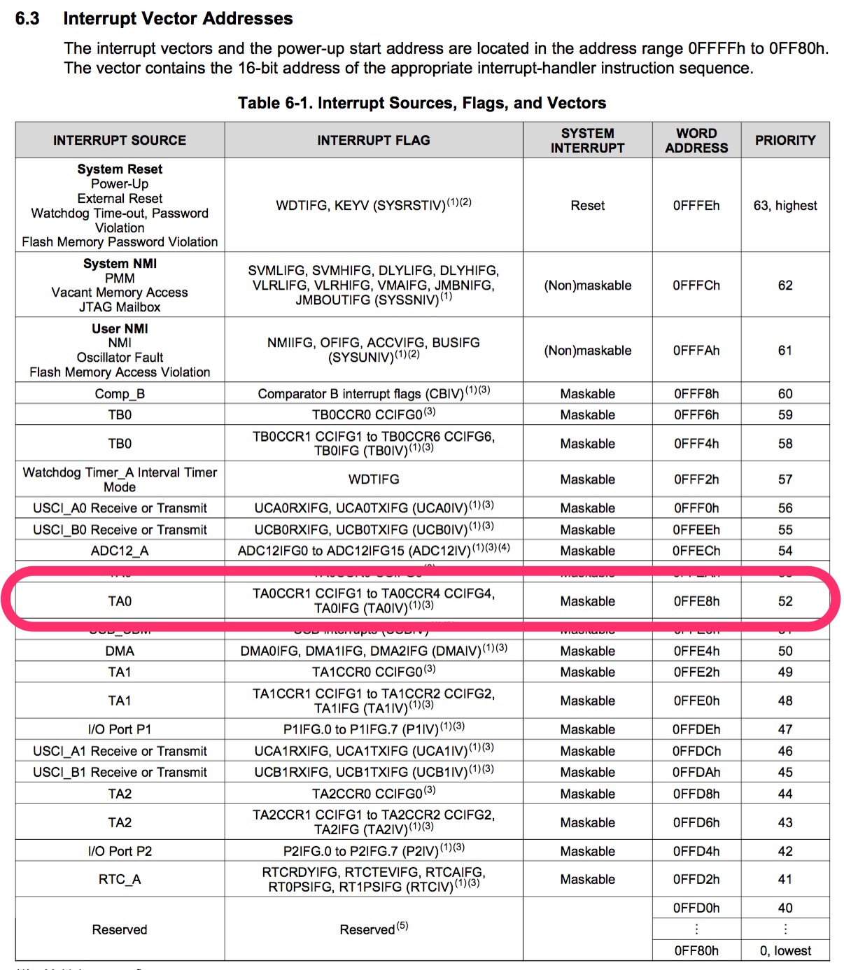
That “52” at the end of the TA0 line means that The MSP430 calls the interrupt “interrupt 52.” We connect interrupt 52 to the TA0_ISR function we just wrote like this:
;-------------------------------------------------------------------------------
; Interrupt Vectors
;-------------------------------------------------------------------------------
            .sect   ".reset"                ; MSP430 RESET Vector
            .short  RESET
            .sect   ".int52"
            .short  TA0_ISR
The reset stuff was already there; we added the last two lines about .int52 and TA0_ISR.
Those two lines tell the microcontroller that when interrupt 52 happens (aka the TA0 interrupt), then call the function named TA0_ISR.
If you need a reminder of that all that .sect and .short stuff is about please read the introduction to interrupts a few posts ago. That post used int47 and PORT1_ISR in exactly the same way we just used int52 and TA0_ISR.
If you compile and download this code onto your MSP430 LaunchPad, when you run it you should see the LED blinking on and off every two seconds or so. You’ve configured and used your first timer! Cool, eh?
Here’s all the code in one place so you can copy and paste it into your Code Composer Studio session if you like:
;-------------------------------------------------------------------------------
           ; Set GPIO P1.0 to be an output
           BIS.B      #1, &PADIR_L

           ; Enable interrupts
           NOP
           BIS #GIE, SR
           NOP

           ; Configure ACLK as the timer clock source, with both the
           ; ID and IDEX dividers set to /1.
           ; ACLK runs at 32768 Hz, and so will the timer.
           ; (UCSCTL4.SELA == 0 means use XT1 which is a 32.768 KHz xtal,
           ;  UCSCTL5.DIVA === 0 means div-by-1 so ACLK is == 32768 Hz.)
           BIS #TASSEL_1, &TA0CTL   ; TASSEL == 1 selects ACLK
           BIS #ID_0, &TA0CTL       ; ID == 0 selects /1
           BIS #TAIDEX_0, &TA0EX0   ; IDEX == 0 selects /1

           ; Configure timer to interrupt on overflow.
           BIS #TAIE, &TA0CTL

           ; Configure timer in continuous mode.
           ; Setting MC to anything other than 0 also starts the timer, so we
           ; want to do this as the last timer configuration step.
           BIS #MC_2, &TA0CTL       ; MC == 2 selects continuous mode

MainLoop:  ; Do nothing, all action is in the interrupt
           JMP MainLoop

TA0_ISR:
           ; Clear the interrupt flag.
           BIC #TAIFG, &TA0CTL

           ; Toggle GPIO P1.0
           XOR.B      #1, &PAOUT_L

           RETI

;-------------------------------------------------------------------------------
; Stack Pointer definition
;-------------------------------------------------------------------------------
            .global __STACK_END
            .sect   .stack

;-------------------------------------------------------------------------------
; Interrupt Vectors
;-------------------------------------------------------------------------------
            .sect   ".reset"                ; MSP430 RESET Vector
            .short  RESET
            .sect   ".int52"
            .short  TA0_ISR
This post is part of a series. Check out the complete Embedded Software Engineering 101 series here.