
Discovery: Buttons
Last time we looked at the simplest peripheral on our development boards, the LED. This time we will take the complexity up slightly and look at the push button.
How complex can this be? Being a human interface device, a button has to act in a way that humans feel is correct. We’ve all experienced buttons that may work properly for the computer, but don’t feel right to us. They might not register our push, or register multiple times on a single push, let’s look at the causes for these situations and what can be done about them.
I’m Sorry, I Missed That
When you push a button connected to a processor, the processor has to notice that the button has been pushed. How does it do that? First some background, our processor is given two voltages: 3.3 volts (also known as VDD) and 0 volts (otherwise known as ground or VSS notated as a stripey arrow pointing down). Now assume that our electricity will flow from positive to negative (just believe it, don’t argue).

Figure 1
Our little cartoon circuit in figure 1 is called a schematic. It does not show precisely how the circuit is laid out on the circuit board, but it is a good enough representation, all of the important elements are there. Much like XKCD has stick figures to represent people with enough precision to tell a joke, schematics represent a circuit board with enough precision to describe a circuit.
In figure 1, we see the processor pin PA0 (port A, pin zero) on the left. That is the pin the processor will be sampling to see what voltage is present. With this circuit, if the processor has a voltage roughly equal to VDD on the pin, the circuitry interprets this as a “1” in the GPIO port A input data register. If the voltage is roughly equal to ground, the circuitry interprets this as a “0” in register.
On our board, the button (the blue one on the real board) is called B1, and if you look at figure 1, you can see B1 over on the right side with two circles and a bar. These are the contacts, and hovering beside them, but not connected, is a bar. When a stick man pushes the button, the bar will connect the circles, completing the circuit. The switch has 4 contacts numbered 1, 2, 3, and 4. Within the switch contacts 1 and 4 are connected, and 2 and 3 are connected, as illustrated by the lines between the contact pairs. In schematics, switches are drawn in their normal configuration when a stick man is not pushing the buttons. Our button has an air gap drawn, and we say that it is “normally open”.
In the real switch there are two sets of metal contacts and a conductive plate that is bent like a spring. When you press the button, the plate touches the contacts allowing electricity to flow through the switch. If the button is not pressed, there is an air gap between the plate and the contacts and electricity will not flow across the gap.
With the button open there are two possible paths for current to take; through the switch or through a resistor and a capacitor.
VDD can go to pins 1 and 4 on the switch, but then it cannot bridge the air gap of the switch to get to pins 2 and 3 so the current stops. The air gap, when dealing with these small voltages, can be considered a really big resistance like gigaohms per millimeter, so the amount of current available to go to the processor would be 3.3 volts / billions = effectively nothing.

The other path is to go through resistor R38 and charge up capacitor C38. In this circuit, we are working with direct current (DC), like from a battery, and DC doesn’t flow through capacitors except for a very small amount of leakage, and the electricity once again stops.
So the two possible paths for VDD cannot flow enough electricity to the processor to be detected.

The connection to ground, on the other hand, is across the solder bridge SB20 (just a blob of solder), through R35, then through R39. Any electricity in that part of the circuit will be bled off to ground leaving PA0 at a voltage equal to ground. With a hand waving argument and without explaining resistors, when the button is not pressed the processor pin is connected to ground and the processor will give our program a “0”.

With the button closed (pressed) VDD can flow through pins 1 and 4 on the switch, to pins 2 and 3, across to resistor R35, across the solder bridge SB20, and then to the processor pin PA0. Once again, with our hand waving argument, the processor will give our program a “1”.

Wait, wait, won’t VDD also cross the switch, go down R39 and go to ground???? Isn’t that a short circuit??? Well, yes, but that path will only allow 3.3 volts / 220,000 ohms = 0.000015 amps = 15 microamps to flow. This is an exceedingly small amount of current. On the other hand, going to the processor across R35, we get 3.3 volts / 330 ohms = 0.01 amps = 10 milliamps.
In summary, the idea is that when the button gets pushed, we get 3.3 volts applied to the processor pin. When the button is not being pushed, we get 0 volts applied to the processor pin.
Wait, A Bug!
In preparing this blog entry, I noticed that when ST generated the support project for the STM32F407G-DISC1 circuit board that we are using, they forgot to include the button. So, let’s add it back in. (I have reported the omission to ST, it might get fixed in a future release of the Cortex-F4 library code.)
Down in the bottom-left corner of the chip, click on PA0.
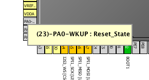
And choose GPIO_Input from the list. Cube has now been told that pin PA0 will be used as an input, it will take care of enabling the clock circuitry to PORT A, setting up the registers so that bit 0 will be an input, and turning off the pull-ups and pull-down resistors.

Then we should give it a name so it shows up in the main.h file. Right-click on the pin…

And enter a name. I used “B1 (Blue PushButton)” like the DiscoveryF4 board had.

“B1” will be used to generate the main.h symbols. The piece in parentheses is ignored and is just used as annotation for the next time you go into Cube and ask yourself why the heck you called something “B1” instead of something reasonable?
To The Polls!
The GPIO port hardware takes care of detecting the voltage on the pins, and converting it into a 1 if there was 3.3 volts, and 0 if there was 0 volts. Next, our program reads the GPIO port register so that we can react to the button.
We use the Hardware Abstraction Layer (HAL) routine HAL_GPIO_ReadPin to get the state of the pin. This routine will return GPIO_PIN_SET if the bit is 1, and GPIO_PIN_RESET if the bit is 0.
It looks like this [1]:
if (GPIO_PIN_SET == HAL_GPIO_ReadPin( B1_GPIO_Port, B1_Pin)) {
   // Do stuff, and see the note at the end of the post.
}
The hard part is deciding when to read the port. To be absolutely sure to read the pin when the human is pushing the button, would mean that we would have to be continually reading the pin. This doesn’t leave us any time to get anything else done.
An alternative would be to understand that computers are fast and humans are slow and we can periodically check the button while doing other stuff. This is known as polling. Much like a 5 year old asking “are we there yet?” We have to poll often enough to be able to detect when the human is pressing the button but not so often that we never get anything else done, and not so seldom that the human can press the button and release it between our polls.
Elecia White, in her article about a Karaoke machine, says "buttons should be handled in less than 250 milliseconds, a quarter of a second." That wouldn't be a difficult deadline to meet. But it really depends on what the button is doing, what or who is doing the pressing, how much processor time you have available, and how much power is available.
Homework
Generate a new project, set up PA0 for the button as shown above, then write a bit of a program that toggles one of the LEDs if the button is pressed. See if you get any odd results.
Next week we will talk about bouncing buttons and how to fix them.
[1] Sometimes programmers will write their if statements backwards, if (42 == x). That is because C is stupid with the == comparisons and the backwards notation can catch one particular mistake: if (x = 42). This is an assignment and this if statement will always be true. If we use backwards notation: if (42 = x), this statement won’t compile. You will get some cryptic error message saying that the assignment must have an lvalue.
This post is part of a series. Please see the other posts here.
This week’s music to work by: The album Blue Train by John Coltrane on Blue Note records
